SERVICE MANUAL
  Applies to: Hyundai Coupe/Tiburon 1998-2000
GROUP
Fuel System MFI Control System
Return to Main Menu(s):      Mechanical Manual      Electrical Manual

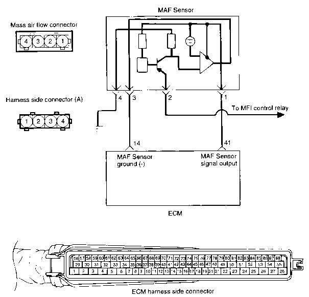
CIRCUIT DIAGRAM 
Return to Main Menu(s):      Mechanical Manual      Electrical Manual

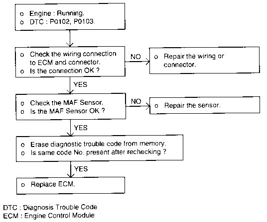
DTC - P0102, P0103 (MAF SENSOR) 
TROUBLESHOOTING HINTS
  1. If the engine stalls occasionally, start the engine and shake the MAF sensor harness. If the engine stalls, check for poor contact at the MAF sensor connector.

  1. If the MAF sensor output voltage is other than 0 when the ignition switch is turned on (do not start the engine). Check for the faulty MAF sensor or ECM.

  1. If the engine can be idle even if the MAF sensor output voltage is out of specification, check for the following conditions;

    • Disturbed air flow in the MAF sensor, disconnected air duct, and clogged air cleaner filter.
    • Poor combustion in the cylinder, faulty ignition plug, ignition coil, injector, and incorrect comparison.
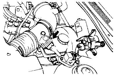
  1. Though no MAF sensor malfunction occurs, check the mounting direction of MAF sensor.

USING VOLTMETER
Check item
Engine state
Test specification
Mass air flow sensor output voltage (MAF sensor side connector No.1 or ECM harness side connector No.41
Idle (800 rpm)
0.7 - 1.1 V
3000 rpm
1.3 - 2.0 V
NOTE
  1. When the vehicle is new [within initial operation of about 500 km (300 miles)], the mass air flow sensor air quantity will be about 10% higher.
  2. Use an accurate digital voltmeter.
  3. Before checking, warm up the engine until the engine coolant temperature reaches 80 to 90°C (176 to 198°F)
Return to Main Menu(s):      Mechanical Manual      Electrical Manual

HARNESS INSPECTION PROCEDURES 
Return to Main Menu(s):      Mechanical Manual      Electrical Manual

MASS AIR FLOW (MAF) SENSOR 

This hot film type air flow sensor is composed of a hot film sensor, housing, metering duct (hybrid, sensor element).

Mass air flow rate is measured by detection of heat transfer from a hot film probe because the change of the mass air flow rate causes change in the amount of heat being transferred from the hot film probe surface to the air flow. The air flow sensor generates a pulse so it repeatedly opens and closes between the 5V voltage supplied from the engine control module. This results in the change of the temperature of the hat film probe and in the change of resistance.