SERVICE MANUAL
  Applies to: Hyundai Coupe/Tiburon 1998-2000
GROUP
Fuel System MFI Control System
Return to Main Menu(s):      Mechanical Manual      Electrical Manual

CRANKSHAFT POSITION SENSOR 

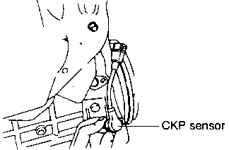
The crankshaft position sensor which consists of a magnet and coil is installed by the flywheel. The voltage signal from this crankshaft position sensor is provided to the ECM for detecting engine RPM and the position of crankshaft.

Return to Main Menu(s):      Mechanical Manual      Electrical Manual

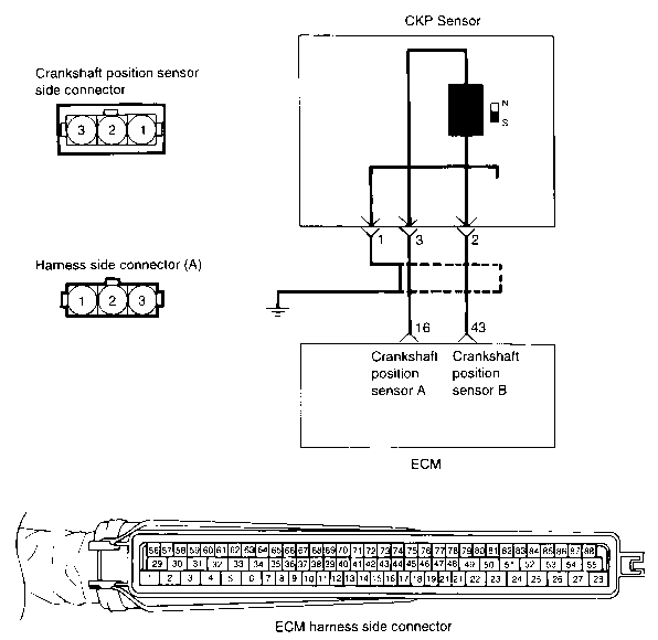
CIRCUIT DIAGRAM 
Return to Main Menu(s):      Mechanical Manual      Electrical Manual

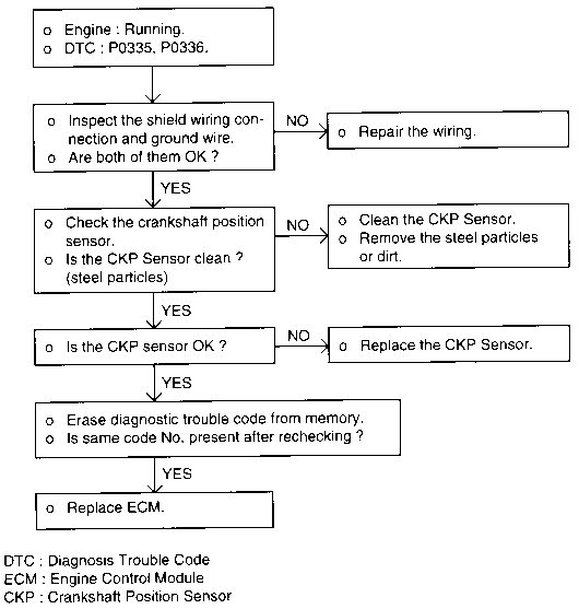
DTC - P0335, P0336 (CRANKSHAFT POSITION SENSOR) 
TROUBLESHOOTING HINTS
  1. If unexpected misses are felt during driving or the engine stalls suddenly, shake the crankshaft position sensor harness. If this causes the engine to stall, check for poor contact at the sensor connector.
  2. If the tachometer reads 0 rpm when the engine is cranked, check for faulty crankshaft position sensor or ignition system problems.
  3. If the tachometer reads 0 rpm when the engine is cranked and it does not start, ignition coil, power TR, or an ECM defect can be considered.
  4. Engine can be stalled when the crankshaft position sensor cable is close to the high voltage cable due to the noise caused by the high voltage induced.
Return to Main Menu(s):      Mechanical Manual      Electrical Manual

HARNESS INSPECTION PROCEDURE 
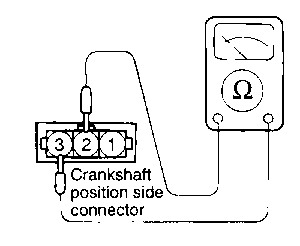
SENSOR INSPECTION
  1. Disconnect the crankshaft position sensor connector.

  1. Measure the resistance between terminal 2 and 3.

    SPECIFICATION
    Standard value 0.486-0.594 kO at 20°C (68°F)
  1. If the resistance deviates far from the standard value, replace the sensor.

    SPECIFICATION
    Clearance between the crankshaft position sensor and crankshaft position sensor wheel 0.5-1.5 mm (0.020-0.059 in.)
    TORQUE SPECIFICATION
    Crankshaft position sensor 9-11 Nm ( 90-110 kg·cm, 6.6-8.1 lb·ft )