SERVICE MANUAL
  Applies to: Hyundai Coupe/Tiburon 1998-2000
GROUP
Transaxle/Transmission Automatic Transaxle System
Return to Main Menu(s):      Mechanical Manual      Electrical Manual

CHECKING PROCEDURE (SELF-DIAGNOSIS) 
NOTE
  • As many as ten diagnostic trouble codes, in the sequence of occurrence, can be stored in the Random Access Memory (RAM) incorporated within the control module.
  • The same diagnostic trouble code can be stored just one time.
  • If the number of stored diagnostic trouble codes or diagnostic trouble patterns exceeds ten, already stored diagnostic trouble codes will be erased, in sequence beginning with the oldest.
  • Do not disconnect the battery until all diagnostic trouble codes or diagnostic trouble patterns have been read out, because all stored diagnostic trouble codes or diagnostic trouble patterns will be canceled when the battery is disconnected.
  • If the auto transaxle fluid temperature reaches over 50°C and 200 times from the initial memory, the fault code will be erased.
  • If the fail-safe system is activated and the transaxle is locked in third gear, the diagnostic trouble code in the Fail Safe Code Description will be stored in the RAM. Three of these fault codes can be stored.
  • The cancelation will occur if, with the transaxle locked in 3rd gear, the ignition key is turned to the OFF position, but the diagnostic trouble code is stored in the RAM.
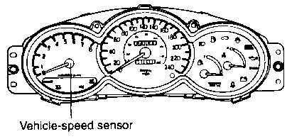
Malfunction Indicator Light (MIL)

A on board diagnostic light comes on to notify the driver that there is any problems on the vehicle. However, when an irregular state returns to normal, the malfunction indicator lamp will go out automatically after 3 driving cycles that have no same fault. Immediately after the ignition switch is turn on, the malfunction indicator light is lit for continuously to indicate that the malfunction indicator light operates normally.

Following items will be indicated by the MIL.
  • Fluid temperature sensor
  • Pulse generator A (PG-A)
  • Pulse generator B (PG-B)
  • Shift control solenoid valve A (SCSV-A)
  • Shift control solenoid valve B (SCSV-B)
  • Pressure control solenoid valve (PCSV)
  • Damper clutch control solenoid valve (DCCSV)
  • Shift stage synchronizer
  • Ignition pulse
  • Throttle position sensor
  • Transaxle range switch
INSPECTION PROCEDURE FOR DIAGNOSTIC TROUBLE CODES
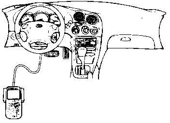
USING HI-SCAN
  1. Turn OFF the ignition switch.

  1. Connect the scan tool to the data link connector.

  1. Turn ON the ignition switch.

  1. Use the scan tool to check the diagnostic trouble code.

  1. Repair the faulty part from the diagnosis chart.

  1. Erase the diagnostic trouble code.

  1. Disconnect the scan tool.

USING VOLTMETER
  1. Ignition switch ON (Do not start).

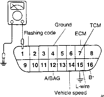
  1. Connect the voltmeter to the data link connector (No. 1 pin).

  1. Ground the L-wire (No. 15) in the data link connector.

  1. Output pattern shows on the voltmeter.

  1. Read the output diagnostic trouble codes. Then follow the remedy procedures according to the "DIAGNOSTIC TROUBLE CODE DESCRIPTION" on the following page.

  1. Erase the diagnostic trouble code.