SERVICE MANUAL
  Applies to: Hyundai Coupe/Tiburon 1998-2000
GROUP
Heating, Ventilation & Air Conditioning Heater
Return to Main Menu(s):      Mechanical Manual      Electrical Manual

COMPONENTS 
Return to Main Menu(s):      Mechanical Manual      Electrical Manual

REMOVAL 
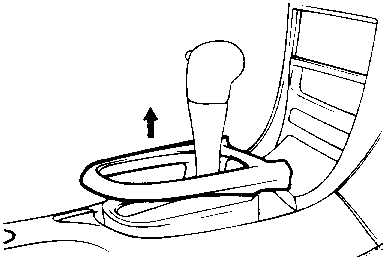
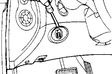
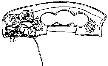
  1. Remove the shift lever upper cover.

  1. Remove the facia panel mounting screws.

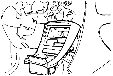
  1. Remove the floor console mounting screws (4EA) and then, remove the floor console.

  1. Disconnect the rheostat switch.

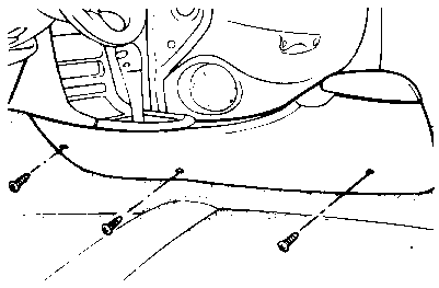
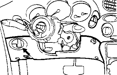
  1. Remove the lower crash pad panel.

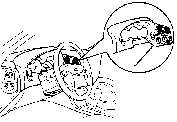
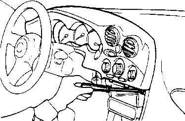
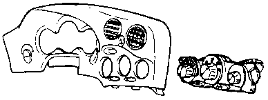
  1. Remove the cluster facia panel mounting screws (5EA) from the cluster facia panel.

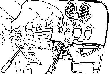
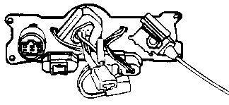
  1. Pull out the cluster facia panel, disconnect switch extension wire connector, vacuum harness connector, blowers switch connector, A/C switch connector.

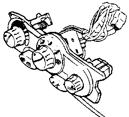
  1. Remove the heater control panel mounting screws.

  1. Remove the heater control panel assembly from the cluster facia panel.

Return to Main Menu(s):      Mechanical Manual      Electrical Manual

DESCRIPTION 

The heater assembly is a blend air system and consists of a heater assembly, blower assembly and duct which is connected between the heater case and blower case. The heater case contains the heater core and the temperature blend door. The blower assembly containing the outside/recirculating air door, the blower motor and the lower wheel is connected directly to an opening in the upper cowl. The outside air is drawn into the system from the cowl through the blower inlet into the blower housing, forced through and/or around the heater core, mixed and then discharged through outlets in the discharge air duct to the floor area or through the defroster outlets depending the type of climate control desired. The system airflow is controlled by two kind of control assembles, the vacuum rotary and the manual lever type.

Return to Main Menu(s):      Mechanical Manual      Electrical Manual

INSTALLATION 

Installation is the reverse order of removal.

TEMPERATURE CONTROL CABLE ADJUSTMENT

After installation of the heater control assembly, adjust the temperature control cable.

  1. Slide the temperature control lever to HOT.

  1. Turn the temperature door shaft arm to the left and connect the end of the cable to the arm.

  1. Gently slide the cable outer housing back from the end enough to take up any slack in the cable, but not enough to make temperature control lever move, then snap the cable housing into the clamp.

Return to Main Menu(s):      Mechanical Manual      Electrical Manual

INSPECTION 
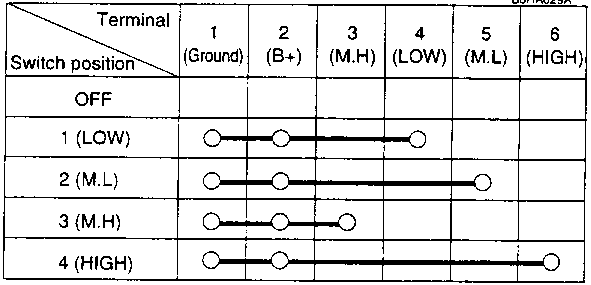
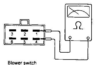
BLOWER SWITCH
  1. Check for continuity between terminals as shown below.

If continuity is not as specified, replace the switch.

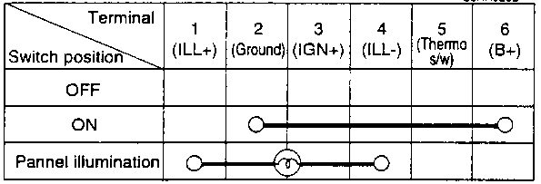
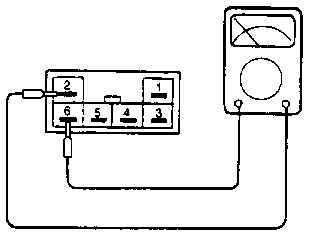
AIR CONDITIONING SWITCH
  1. Check for continuity between terminals as shown below.

If continuity is not as specified, replace the switch.

MODE CONTROL SWITCH
  1. Connect the vacuum tester to black color hose of the vacuum connector.

  1. Connect the vacuum hoses to mode control switch.

  1. Clog the vacuum port for fresh/recirc control switch.

  1. Check for vacuum hiss from the mode switch and vacuum hoses, and inspect for air flow between each hoses when the mode switch is at the each positions as shown below.

    Hose
    color
    Panel
    Panel/
    Floor
    Floor
    Floor/
    Defroster
    Defroster
    Black
    V
    V
    V
    V
    V
    Blue
    -
    V
    V
    V
    -
    Red
    -
    -
    V
    -
    -
    Yellow
    V
    V
    -
    -
    -
    White
    -
    -
    -
    -
    -
    NOTE
    'V': make air flow with black hose.

If air flow is not as specified, replace the mode switch.

FRESH/RECIRC BUTTON
  1. Connect the vacuum tester to back color hose for the fresh/recirc control switch.

  1. Check for vacuum hiss and air flow as shown below.

    Hose color
    Button switch position
    Fresh
    Button switch position
    Recirc
    Black
    V
    V
    White
    -
    V