SERVICE MANUAL
  Applies to: Hyundai Coupe/Tiburon 1998-2000
GROUP
Fuel System MFI Control System
Return to Main Menu(s):      Mechanical Manual      Electrical Manual

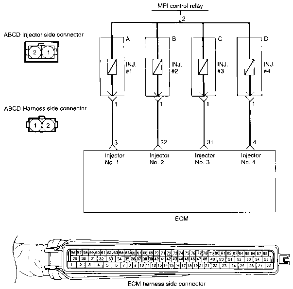
CIRCUIT DIAGRAM 
Return to Main Menu(s):      Mechanical Manual      Electrical Manual

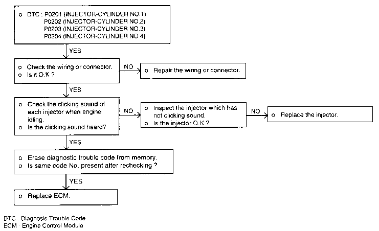
DTC - P0201, P0202, P0203, P0204 (FUEL INJECTOR) 
TROUBLESHOOTING HINTS
  1. If the engine is hard to start when hot, check for fuel pressure and injector leaks.

  1. If the injector does not operate when the engine is cranked, then check the following:

    • Faulty power supply circuit to the ECM and faulty ground circuit
    • Faulty MFI control relay
    • Faulty crankshaft position sensor and camshaft position sensor
  1. If there is any cylinder whose idle state remains unchanged when the fuel injection of injectors is cut one after another during idling, check for the following items about such cylinder.

    • Injector and harness
    • Ignition plug and high tension cable
    • Compression pressure
  1. If the injection system is OK but the injector drive time is out of specification, check for the following items.

    • Poor combustion in the cylinder. (faulty ignition plug, ignition coil, compression pressure and etc.)
  1. The MIL is on or the DTC is displayed on the SCAN TOOL under the following condition.

    • When the injector itself is faulty
Return to Main Menu(s):      Mechanical Manual      Electrical Manual

FUEL INJECTOR 

The injectors inject fuel according to a signal coming from the ECM. The volume of fuel injected by the injector is determined by the time the solenoid valve is energized.

Return to Main Menu(s):      Mechanical Manual      Electrical Manual

HARNESS INSPECTION PROCEDURES 
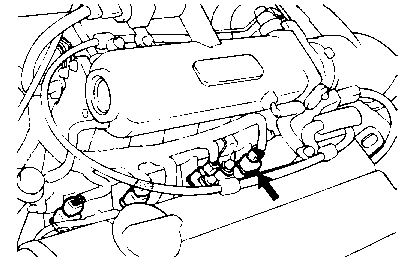
  1. Operation Sound Check
    Using a stethoscope, check the injectors for a clicking sound at idle. Check that the sound is produced at shorter intervals as the engine speed increases.

    NOTE
    Be sure that the sound from an adjacent injector is not being transmitted along the delivery pipe to an inoperative injector.
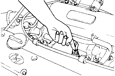
  1. If a stethoscope is not available, check the injector operation with your finger. If no vibrations are felt, check the wiring connector, injector, or injection signal from ECM.

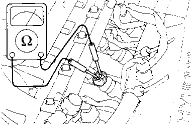
  1. Resistance Measurement Between Terminals
    Disconnect the connector at the injector.

  1. Measure the resistance between terminals.

    SPECIFICATION
    Standard value 15.9±0.35 [at 20°C (68°F)]
  1. If the resistance is not within specification, replace the injector.