


 |
Internet-Enabled Cat
Feeder (The World's First IPv6 Cat Feeder!) |
 |
 Ranked #2 in in
Mac|Life Magazine's Top Ten Wonders of the Home
Automation World ! (Mar
'10, pp 30-31)
Ranked #2 in in
Mac|Life Magazine's Top Ten Wonders of the Home
Automation World ! (Mar
'10, pp 30-31)
 |
 (Click
photos to see larger versions. Full-size originals available on
request)
|
 |
 |
 |
|
      |
||
 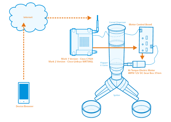  System graphic and WM interface illustrations courtesy of Indra Di Rossche |
||
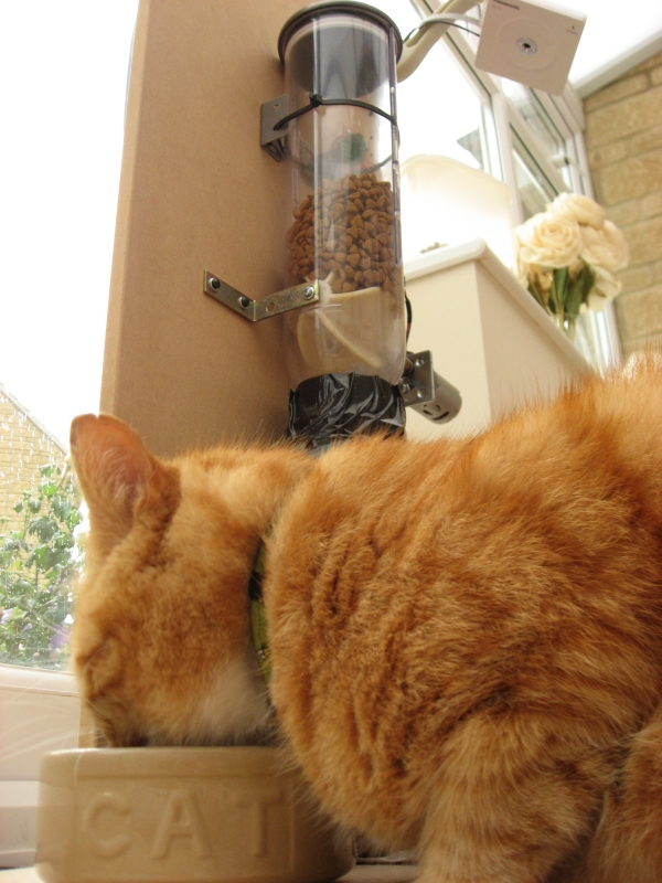
 Flapper - Left View |
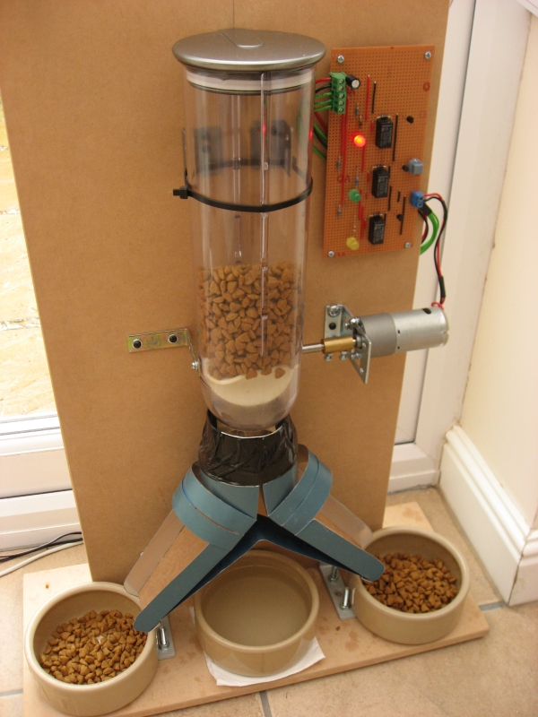
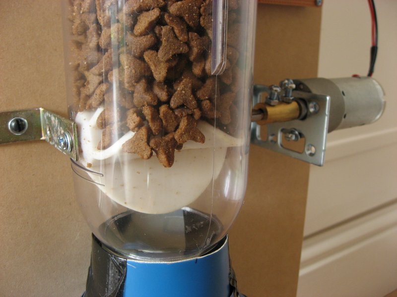
 Dispenser |
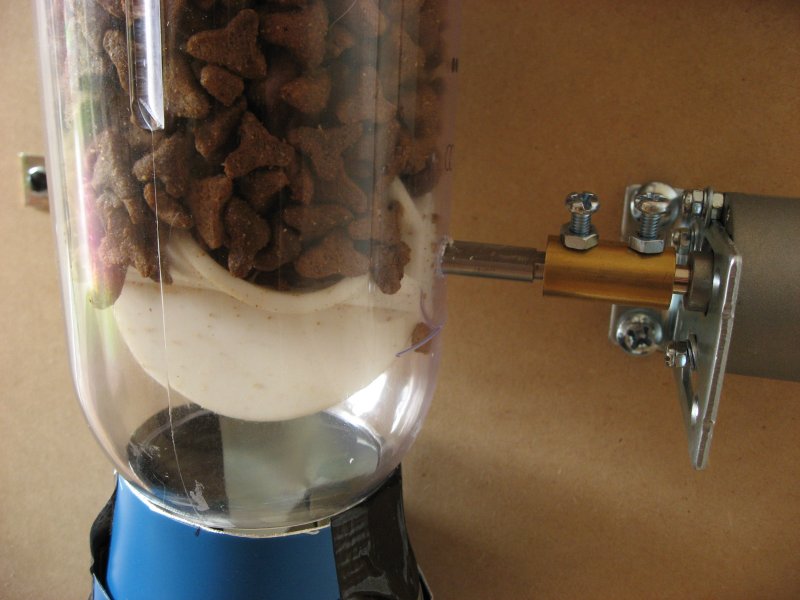 Flapper - Right View |
 Shaft - Top View |
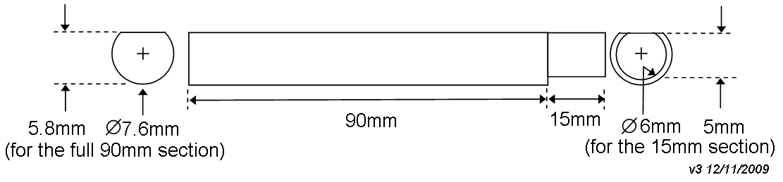 Shaft Drawing |
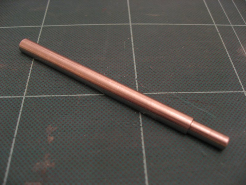 Shaft - Bottom View |
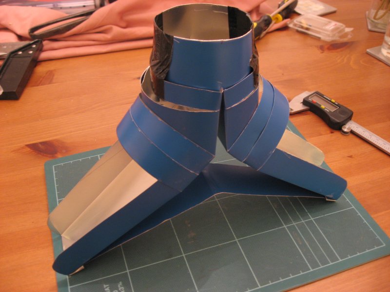 Splitter - Side View |
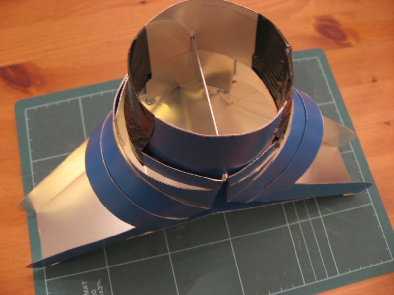 Splitter - Top View |
 Splitter - In Situ |
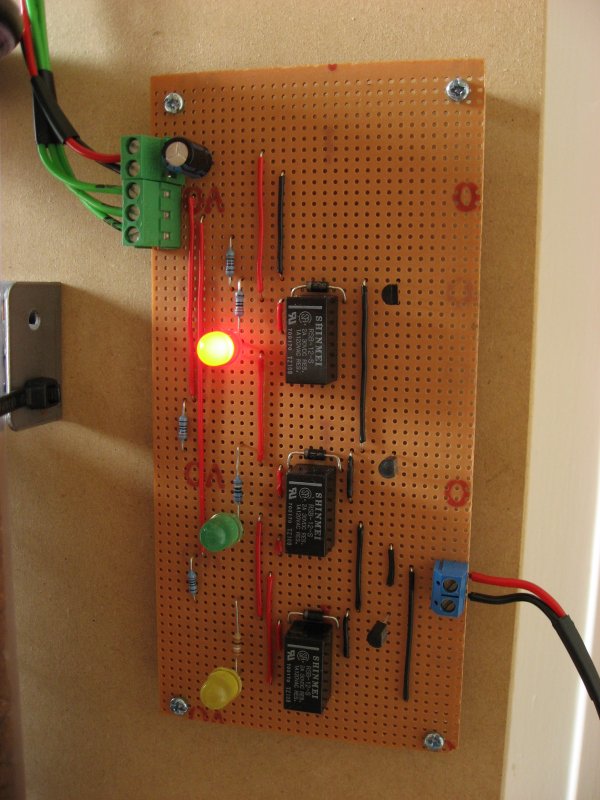
 HC595A Shift Registers |
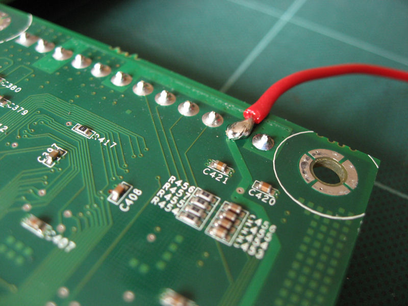
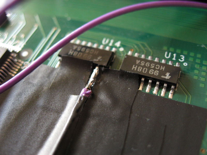 LED Driver Output (Port 20 in this case) |
 Power Sourced from Main Power Block |
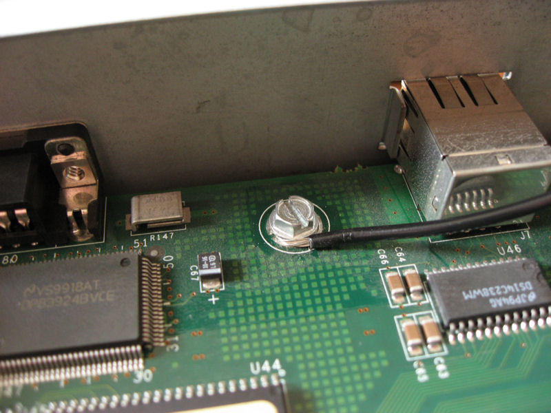 Ground Obtained from Chassis Screw |
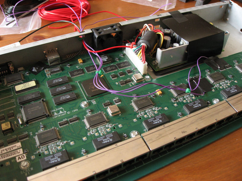 Completed Wiring |
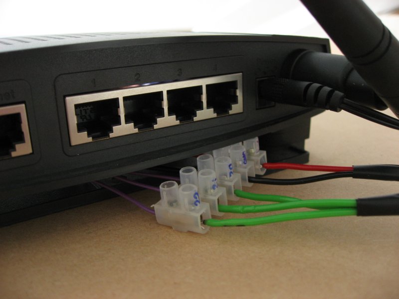
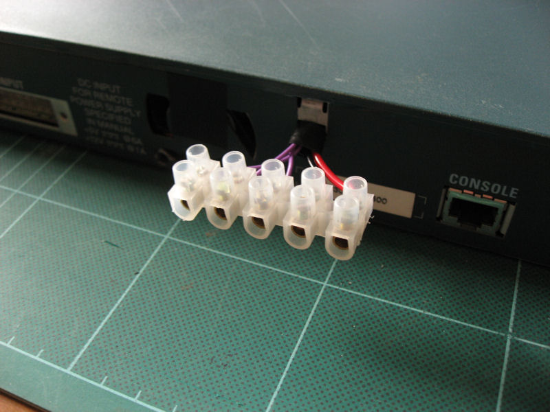 Terminal Block for External Connections |
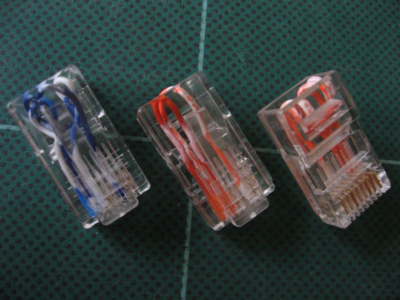 RJ45 Loopback Adapters |
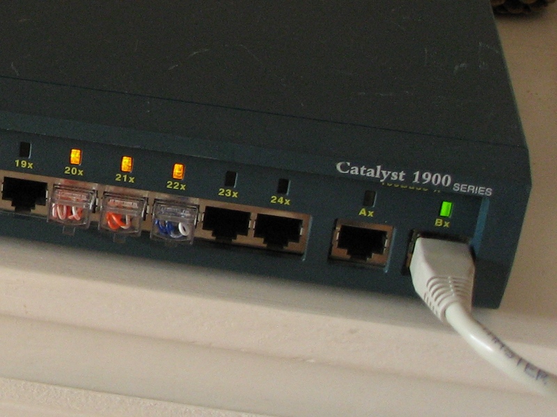 Port Status LEDs |
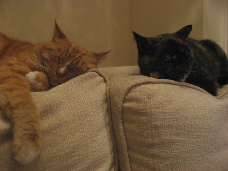
 World IPv6 Day
has been and gone, and Frankie and Elmo are back to two meals a
day! World IPv6 Day
has been and gone, and Frankie and Elmo are back to two meals a
day!On the 8th June 2011,
the Internet Society
along with many
of the 'Internet giants', took part
in 'World IPv6 Day' - a first-of-its-kind event in the history of the
Internet that enabled a large scale test of the 'new Internet
protocol', IPv6.
The event saw a mass enabling of IPv6
by those participating (content providers, transit providers,
ISPs and end users) in order to give the protocol a run for its money
to see what worked, and of course what didn't!
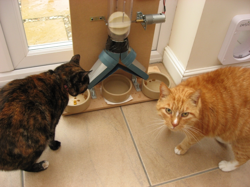
What was my contribution to this unique event? Well, in addition to taking part in a user trial of native IPv6 connectivity provided by my ISP (Plusnet) I also opened up control of my cat feeder - the world's first to support IPv6 - to anyone that cared to give my cats a treat. Anyone, that is, that had IPv6 connectivity of course... ;-) Why? Good question... I could say it was to help demonstrate in a practical way how more and more devices are being hooked up to the Internet in such numbers that the dwindling pool of IPv4 addresses simply cannot hope to accomodate them, or that how such devices can be connected with relative ease given the lack of NAT configuration, port forwarding, etc. However, truth be told, it was mainly just a bit of fun... So, how did it go? Well, very well in fact. Our cats thought Christmas had come early so it was a real success in their eyes, and they still don't know what IPv6 is! But that's the point - IPv6 is an enabler, something that operates behind the scenes, and shouldn't be the concern of the typical end user (admittedly cats probably don't fit that profile... yet). Was/is IPv6 worth it then? Well, put it this way: Prior to the 8th June the cat feeder would, typically, feed the cats twice in 24hrs... On World IPv6 Day they were fed 168 times from all over the world by those with IPv6 so a quick calculation reveals that IPv6 is 84 times better than IPv4. Fact. ;-) The amount of IPv6 seen worldwide accounted for 0.04% of overall traffic on that day and, accordingly, there were 1000's of 'read only' visitors to the catfeeder coming in over IPv4 but we've got to start somewhere so all-in-all the day was quite a success! |
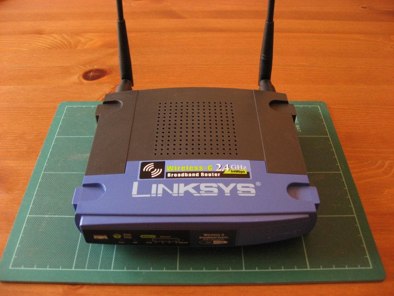 Linksys WRT54GL Router - 'Pre Op' |
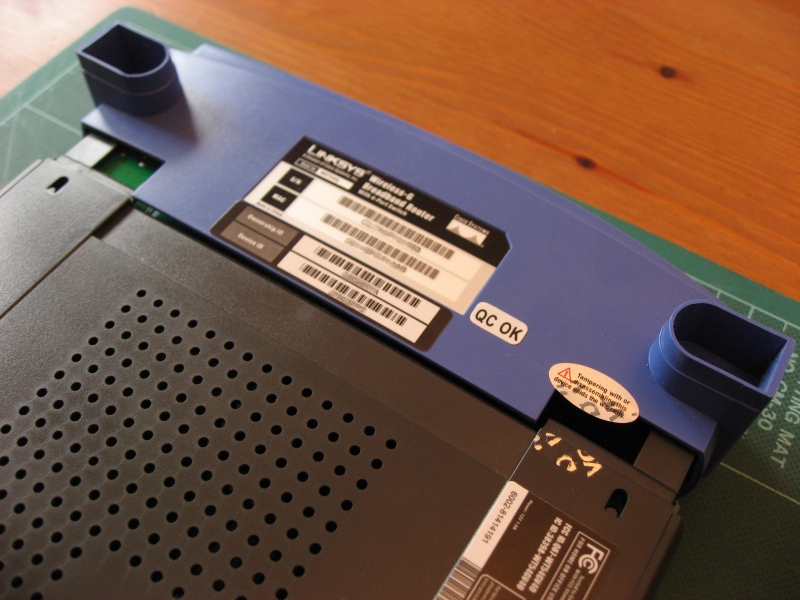 Case Dismantling (Screwless) |
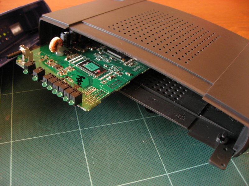 Router Innards |
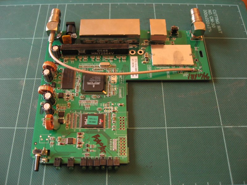 PCB Removed from Case |
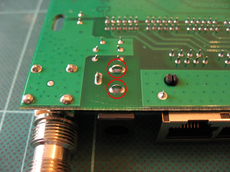 +12v (Top) and GND (Bottom) Connection Points |
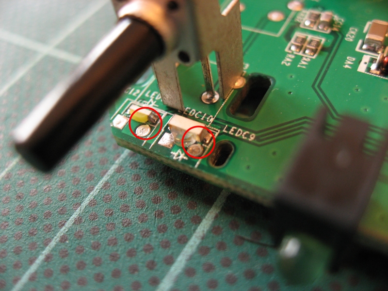 White LED (Left) and Orange LED (Right) Connection Points |
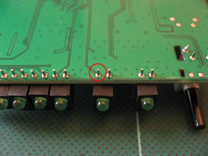 DMZ LED Connection Point |
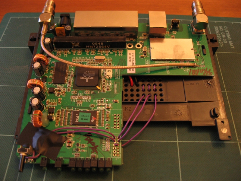 Completed Wiring (Looped through holes for strain relief) |
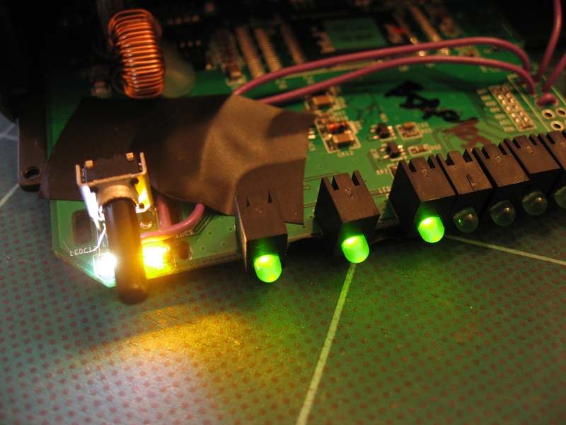 Pre-rebuild
Testing
|
 External
LED View
|
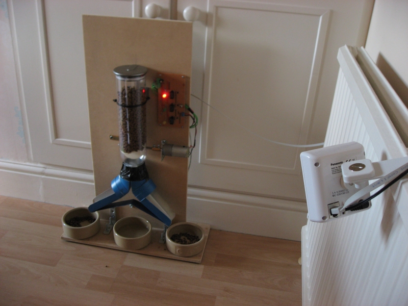
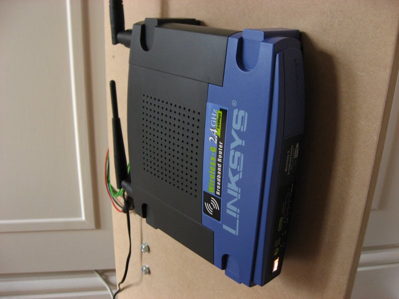 Mounted on
Rear of Feeder
|
 External Connections |
 Circuit Schematic (PDF) |
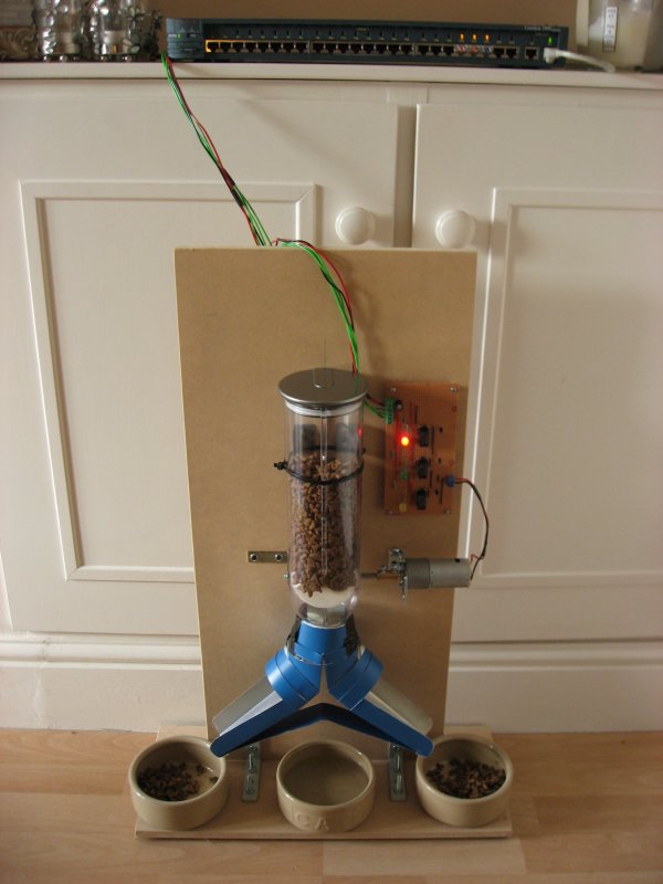
Mounted Control Board |
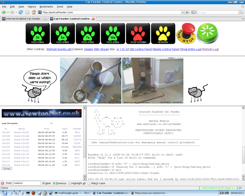
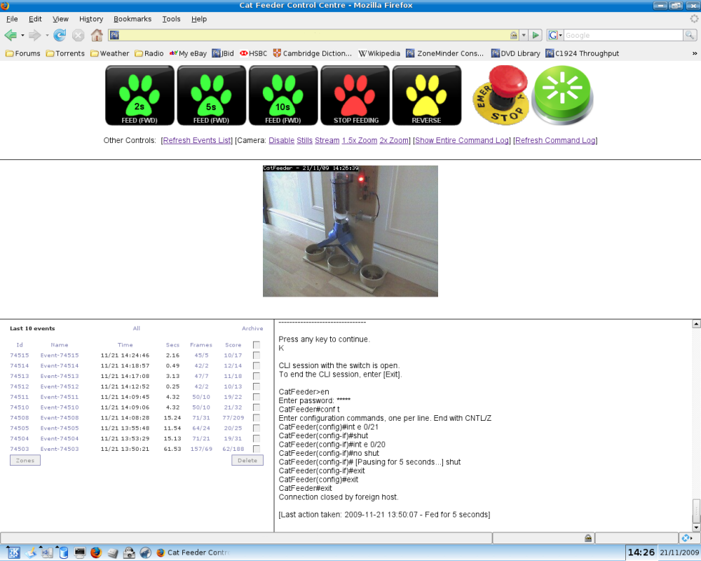 Standard Web Interface |
Dual-Screen Version for World IPv6 Day |
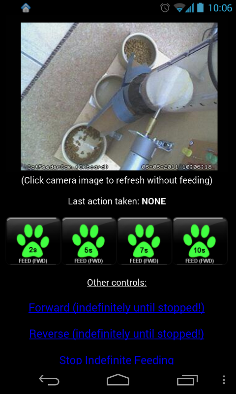
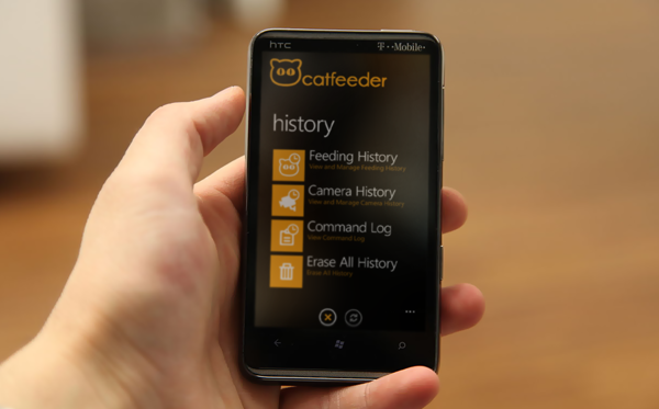
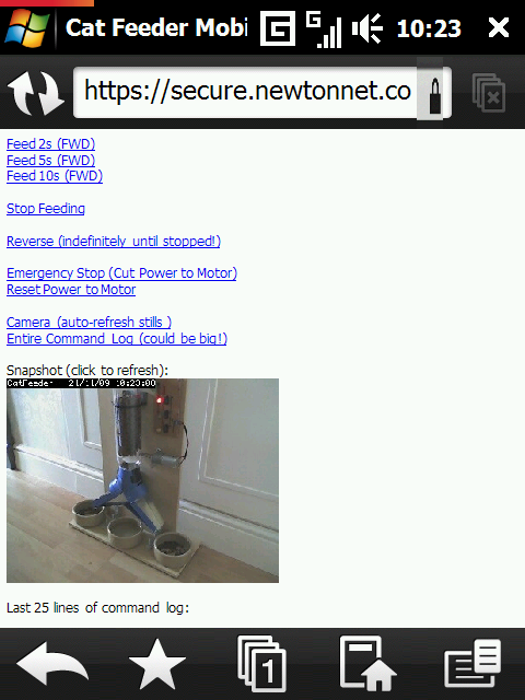 Windows Mobile 'Lite' Interface |
Android App
|
 IP Camera (It was later mounted on the feeder itself) |
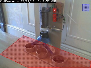 Motion
Detection 'Zones'
|
 Zone Configuration |