


(You
can see my other 'HowTo' guides here)
Preface
Ever since the banning of asbestos in brake pads the substances used to
maintain sufficient braking properties (e.g. high friction, resistance
to heat etc) have resulted in pads/linings being far harder than they
used to be with the net result that discs tend not to last as long
these days. Hence, you may find you're having to replace the discs
(fronts at least) every 40k miles, or less. The job is not all that
difficult as, like most jobs on the car, if you take the time to try
and understand how the system works and break it down into smaller more
manageble steps then it's well within the scope of an average DIYer.
First and foremost however you must remember that the brakes
are
arguably one of the most safety critical parts of a car and hence the
utmost care should be taken when working with them. If you are in any
doubt about your ability to carry out the work to a high safe standard
then leave it to the pros - you cannot put a price on life. That said,
changing the discs and pads is a relatively simple procedure and does
not require any disruption to the hydraulic side of the braking system
and hence as long as you put back all the bolts you remove then you
really can't go far wrong. If you want to err on the side of caution
then don't change all four corners at once - start off with just the
rears and see how you go as they are less critical than the fronts -
relatively at least, in absolute terms they're still essential!
Pads and discs must
be replaced in pairs (i.e. both sides of the same axle) otherwise you
might end up with uneven braking. Fronts and rears can be considered
separate - indeed the fronts wear much quicker than the rears and
usually require more frequent replacement.
I would recommend replacing the pads at the same time as the
discs (and
vice versa) as otherwise you may experience premature wear as the
friction surfaces won't marry up from the start. Besides which, the
costs are relatively affordable for good quality pattern parts to
enable you to change them together thus killing two birds with the one
stone. With regards to the purchase of parts, I can recommend
www.brakepartssuperstore.co.uk for standard discs and pads as their
prices, quality, service and delivery are all good. This is probably an
ideal time to mention the issue of captive
and non-captive discs as,
like you'll see at the aforementioned site and
others, there are two discs listed for the Gen 1 ('96-'02) Coupe with
nothing distinguishing the suitability of each (date alone is
insufficient). Many of the earlier models of the Gen 1 were fitted with
what's known are known as
captive discs on the front - the distinguishing 'feature'
of these discs are that they are fixed to the hub by means of four
large bolts through the hub face. On later models (including all
subsequent generations) these were replaced with the more-standard non-captive discs
which forego the large bolts and rely instead on the wheel itself being
bolted to the hub through disc (note that non-captive discs also have a
small grub screw holding the disc to the hub - this is not a load
bearing fixing but rather simply to keep the disc in place whilst the
wheel is off). So, which have you got? Well, not only do captive discs
have the four bolt heads clearly visible (see Figure 2) but they also
differ in other dimensions as the diagrams below illustrate.
Captive
disc:
(Dimensions: Disc diameter 257mm, Disc thickness: 22mm (20mm service
limit), Overall thickness: 34mm, Hub hole: 86mm)
Non-Captive disc:
(Dimensions: Disc diameter 257mm, Disc thickness: 24mm (22mm service
limit), Overall thickness: 45mm, Hub hole: 69mm)
Why the two types? Well, without going into too much detail (it's
beyond the scope of the purpose of this guide) there are, as always,
pros and cons - captive discs are more securely (and accurately) fixed
to the hub and are designed to be machinable in situ hence a truer
friction face can be achieved. The effect of this is the potential for
more effective braking ability along with fewer vibrations - an
important factor given the tighter tolerances of wheel bearings on
modern cars. However, the downside to this construction method is the
difficulties of maintenance and the requirement of the wheels to
accomodate the bolt heads.
This HowTo has been written primarily based on the Gen 1
however it
will not differ significantly for other generations, and indeed even
other makes and model of car ('standard' ones at least). The
photographs are of the front (with non-captive discs, except Fig 2)
however the differences between that and the rear are minimal and will
be highlighted as required.
The standard rules regarding safety apply - do not work under
a car
supported solely by a jack as they can fail without warning. Ensure the
vehicle weight is supported by suitably placed axle stands (more than
one if possible) and that the remaining wheels are securely chocked.
These measures are of particular importance on this job as there could
well be a fair bit of heaving and heavy hitting required to shift
stubborn components!
Removal
1) Loosen the wheel nuts, chock the wheels (handbrake must be off if
you're doing the rears), jack the car up, removal the wheel and rest
the car on axle stands.
2) Before removing the caliper it is worthwhile sussing out
what's
what and how it all connects together. The principle of caliper
function and operation is essentially quite simple. The caliper can be
broken down into essentially two parts - a movable part that sandwiches
the brake pads between a piston and hard stop, and a static part that
is securely bolted to the car and serves to hold the pads in guides in
the proper position on the face of the disc. The movable and static
halves of the caliper are connected together via sliding guide pins.
Looking at Figure 1 you can make out the movable half of the caliper
(the main 'body' in the centre and right hand side of the whole
caliper), the static half (the taller, thinner, curved section going
from top to bottom) and you can just about see the rubber boot covering
the upper guide pin which connects the two halves together (the lower
pin is not shown). Don't be concerned that your disc doesn't look quite
as shiny as mine... that's the new replacement!
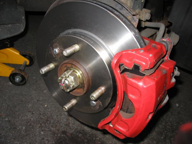
Figure 1 - Disc and caliper (front)
3) There are various ways of actually removing the caliper
in terms of
what order you do things in however for this particular job I recommend
the following. Loosen the two 14mm guide pin bolts but only enough to
shift them - they can be stubborn to move initially (as can all
brake-related components given the environment they operate in) and so
it's beneficial to have the caliper still firmly attached to the car
to allow additional mechanical leverage. Once the guide pin bolts are
loose (i.e. only a single turn or two) then you can proceed to remove
the main 17mm bolts (two of) that secure the static part of the
caliper to the car - again these could take some force to get moving
(a soak in WD40 may help).
4) With the securing bolts removed, lever the caliper
assembly off the
edge of the disc. This will likely require some 'persuasion' as not
only will the pads be a close fit to the disc (for the rears, make sure
the handbrake is off or they'll never budge!) but there could also be a
lip formed on the disc if it is worn (and/or corroded). Wedging a
suitable tool (screwdriver, piece of wood etc) between the edge of the
disc and the caliper (alternating top to bottom) should enable you to
lever it off.
5) Once off, hang the caliper from a suitable point (e.g.
suspension
coil) with some string/cable-ties. Do not let it hang by the brake line
as this can damage it. We'll be partially dismantling it later however
for now we'll leave it alone until we remove the disc - I recommend
doing it this way as if you can't get the disc off then you may end up
having to throw the towel in and take it to a garage and there's no
point in making extra work for yourself by having to reassemble the
caliper.
6) The method of removal of the disc will differ depending on
whether
you've got captive or non-captive discs:
6a) Captive - (early Gen 1's, identifiable by the four lug
holes
and four bolt heads
and the 86mm hub hole as opposed to 69mm) - The disc is actually
positioned behind the hub and is firmly attached using four bolts
passing through the hub from the front. Removal of the disc requires
the outer part of the hub to be dismantled first.
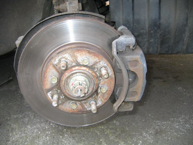
Figure 2 - Captive disc (note the four
bolt heads)
[Photo
courtesy of 'Dodgemeister']
6b) Non-captive (identifiable by the four lug holes and one
(or two)
small screws on the face as per Figure 1) - The discs are positioned in
front of the hub and sandwiched securely between the hub and the wheel
(when fitted). You should see one or two screws holding the disc to the
hub - these serve merely to hold the disc onto the hub whilst the wheel
is off. In true Haynes style, simply remove these. This of course can
usually be translated to mean 'these stubborn buggers will take some
serious work to shift' - I've found the best way, if they are so
stubborn that they can't be shifted with even the biggest force on a
standard screwdriver/wrench, is to use an impact wrench/driver
(<£10 and very handy to have around as you'll be able
to resort to it
before
you've mangled screws/bolts/nuts beyond rescue!). The screw heads
(Philips) are somewhat soft so you may find the head chews before it
even starts to turn. In this case a Dremel-type tool (another
handy-to-have-in-advance tool) can be used to cut a slot in the head to
give the impact drive more purchase with a meaty flat head bit. Heating
the disc may prove futile as it's effectively a huge heatsink and so
you're unlikely to get any reasonable expansion around the thread. If
the worst comes to the worse you'll have to drill them out or lob the
heads off with a cold chisel. Once they're out the disc should now come
away from the hub. Again, in the world of Haynes I'm sure they do
however for everyone else it may require anything from gentle
persuasion with a rubber mallet to full-on wallops with a lump hammer.
Be mindful of the bearings (and of course your eyes!) as whilst they're
tough they're not indestructible. Try initially striking the disc from
the front (on the central face between pairs of wheel lugs) and
spraying WD40 from all angles (particularly behind as it's the hub/disc
mating face that is usually the culprit). For maximum effect any hammer
strikes should be done on opposing sides of the disc in turn bearing in
mind that if the disc starts to twist relative to the face of the hub
this will only add to the difficulty of removal as the wheel lugs will
start to catch on the disc. Persistence will pay off; trust me!
Ultimately the disc might need attacking with an angle grinder and then
striking off with a cold chisel but finger's crossed it doesn't get to
that stage.
7) The brake pads can now be removed from the caliper - this
is best
achieved by removing the 14mm guide pin bolts (you did loosen them in
step 3 didn't you?) and separating the two halves of the caliper.
Leave the movable (piston carrying) part hanging and remove the static
part holding the pads. These will be held in primarily by crud now that
they don't have a disc between them and caliper piston behind them
(they are after all 'floating' in guide rails in order to enable them
to slide in/out and adjust to the disc surface) however they might
still require a tap with a hammer. You will find it easier to remove
them in the direction of each other as the guide brackets are sometimes
shaped to stop them coming out of the back (more to ease reassembly
than anything else). Once out clean the whole lot ensuring that the
crud in the guide rails (where the pad 'ears' were located) is removed.
It's worth inspecting the condition of the guide pin boots at this
stage as if they're perished then it is only a matter of time before
one, or both, of them seize (particularly on the rears where they don't
see much action).
8) Back to the piston part of the caliper (Figure 3) remove
the large
metal plate (only on the rears) if your new pads came with a
replacement - this serves to reduce vibration and brake squeal and is
most required on the rears where less braking force is applied. Then,
clean the caliper (ideally with brake cleaner but whatever you use
make sure you don't damage/bypass the rubber piston seal) and you are
now ready to retract the piston back in to the caliper - this is
necessary given that your new pads and disc will be thicker than the
old ones and hence will require the caliper to be wider if you're to
have any hope of reassembling it all. How this is done depends on
whether you're doing the front or rear however in both cases the job
will be made easier if you loosen the cap on the fluid reservoir (don't
remove the cap entirely - you don't want anything dropping in or it
being exposed to too much air as it is very hydroscopic hence will
absorb any water vapour it can which will ruin braking performance if
it boils). However, be mindful of the fact that if any brake fluid has
been added when the pads were worn then you may find the level rises
above the lid of container - make sure this doesn't get anywhere near
your paint as it's a more effective paint stripper than paint stripper
itself! (wash it off with plenty of water if this happens, oh and try
not to touch the stuff yourself as it's not particularly good for your
health).
8a) Fronts - The piston 'simply' requires pushing back into
the
caliper. Favourite methods vary but I use either a G-clamp, piece of
wood to lever it against the caliper body or a spanner held across the
piston face and pushed from either end etc. Heck, you can even use a
special tool designed for the job. In all cases take it slowly as you
must remember that you're trying to push a relatively large volume of
non-compressible fluid from a wide piston into the narrow bore of the
brake line - at best this can only be achieved at a slow pace. You will
find that once you've started it moving it tends to get easier - you
probably won't see it moving to start with but just persist and keep
telling yourself that it will move! Push until the rubber boot appears
as retracted as it will reasonably get (i.e. so that the piston is
flush with the boot) - you don't really want to push it too far in case
you end up breaking the seal. You can always go back to it if you find
it's not retracted enough when you come to reassemble.
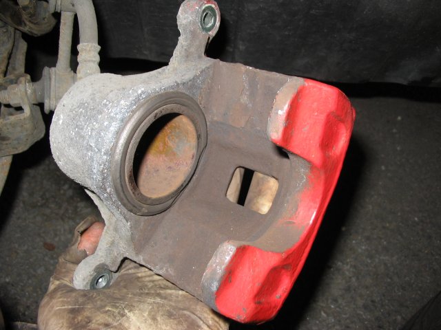
Figure 3 - Movable/Piston half of caliper
(front)
8b) Rears - For these it's the same principle as the fronts
yet with,
quite literally, an added twist. The rears have the handbrake mechanism
built into the back of them consisting of a nut on a threaded shaft (or
a variation thereof). The handbrake pushes the back of the piston via
this self-adjusting mechanism and the nut slowly rotates over time to
make up for the thinning of the pads/disc. To retract the piston you
cannot just push it back in as the mechanism will be right behind the
piston (even with the handbrake off - which, incidentally, you must
make sure is!), instead you have to rotate the piston clockwise whilst
pushing it in - this is easier than it sounds if you use a pair of
needle-nose pliers located in the recesses on the piston face. Again,
take it slowly and you'll gradually start to wind it back in. Just
turning the piston won't get you anywhere (it'll just keep rotating) -
it needs to be pushed in at the same time. Finish off when the piston
is flush and aligned such that the grooves are horizontal to the
caliper body - a lug on the back of the pad will be required to sit
inside one of them (to stop the piston rotating instead of the
self-adjusting nut).
9) It's worth pointing out that at this stage you must not
press the
brake pedal as this will cause the unimpeded piston to be pushed out.
Also, make sure you now replace the cap on the brake reservoir as
you'll forget otherwise and you don't want this stuff splashing around
the engine bay (or being contaminated for that matter).
Replacement
10) The order with which you proceed is open to debate. I prefer to get
the pads ready in the static part of the caliper and on to the car
before reassembling the entire caliper. Try the pads for fit in the
caliper whilst everything is clean to get a feel for how they're going
to go in. They may require some persuasion, particularly if you've
replaced the plate in Step 8 (only for the rears) as there will be
plenty of spring in it. You may also find you need to file the 'ears'
of the pads to make them fit - this is quite common. Don't be worried
about them being a tight fit as if you can just about get them in by
hand then that's ideal - remember the piston force is immense and so
will have no trouble making them slide. If they're too loose you may
find they squeal as they vibrate under load. Check the other side of
the car if you can't work out which way they fit (Figure 4 shows them
fitted if that helps). Just remember two things: i) the friction
material must face inwards (i.e. the the face of the disc)!, and ii)
the pads are curved to fit the shape of the (circular) shape of the
disc. Abiding by these two rules I don't you could really go wrong.
Note also that most pads will come with some sort of anti-squeal
backplate either fitted or in the box so make sure they're ready to be
fitted and also that one pad will likely have a metal audible wear
indicator (a fancy name for a bent piece of metal which starts grinding
away at your disc if the pads get too thin) and so make sure this one
is fitted on the correct side of the caliper (check the other side,
but it's usually on the inner side of the caliper) in case it foulds
anything if placed in the 'wrong' slot.
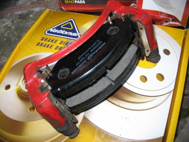
Figure 4 - Pads fitted to static half of
caliper 'dry'
11) Once you're happy you can get the new pads in and that
they fit
you're ready for the proper (re)assembly. To reduce squeal and
corrosion you should apply a coating of copper grease onto the backs of
the pads (and piston face if you like to be thorough) and (optionally)
the metal plates/runners that the pad ears/lugs slide in. Apply it sparingly as you
really
don't want to get any of it on the friction material, either now or
when in use. There is no completely satisfactory way of degreasing a
brake pad - don't let this frighten you but just bear it in mind with
all this grease around. Position the pads in the holder such that there
is sufficient space for the disc to slide between (just about - with
new pads and disc there is not going to be much slack available)
however their exact position will be dictated when the rest of the
caliper is fitted to it.
12) Put the caliper aside for a moment as you're now ready to
fit the
new disc. It will have likely come with a protective coating to stop it
rusting in storage/transit and this should be removed with meths (white
spirit is rather greasy). With it, and the hub face, cleaned and ready
to go smear a light coating of copper grease on the hub face (see
Figure 5) as this will hopefully minimise corrosion and make it much easier to
remove them next time. Again, keep the grease off the disc surface. For
non-captive discs put copper grease on the retaining screw(s) threads
and heads/washers to stop them corroding in place. If you mangled the
screws whilst removing them then you can actually safely leave them out
or replace them (M6x15mm for Gen 1?) [Note: Captive discs will require
a different reassembly as per the reversal of Step 6a). Ideally you
would now check the runout of the disc with a dial-test indicator (to
<0.04mm for Gen 1) and rotating the disc position relative to
the hub until it is straight. In practice, with a clean hub and disc,
you shouldn't have problems. Put it this way - your average grease
monkey would certainly not check them like this.
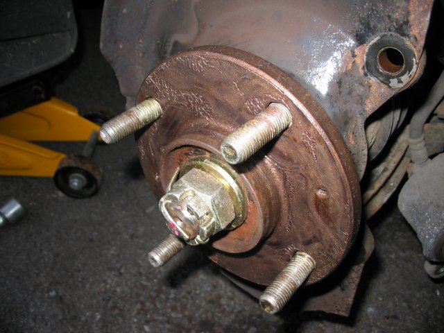
Figure 5 - Greased hub (note that it looks
greasier than it is!)
13) With the disc back on, slide the static part of the
caliper around
the disc (Figure 6). You may find that depending on exactly how you
positioned the pads some adjustment will have to be made in order to
align the caliper with the bolt holes on the knuckle. With it in place
replace the 17mm bolts (tightened to 69-85Nm for the Gen 1).
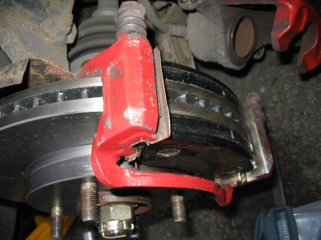
Figure 6 - Static half of caliper
containing the pads fitted around
disc
14) Now it's time to replace the movable (piston) part of the
caliper
around the pads and into place. With the pads pressed against the disc
(check both sides) here is where you find out if you pushed the piston
back in far enough - it could well be a close fit. Note that, for the
rears, you need to ensure that the lug on the back of the pad aligns
with the depression on the piston face (remember this serves to stop
the piston rotating with the handbrake) - there is some room for play
here. Finally, align the guide pins with the bolt holes (noting that
the pins might need rotating to fit - the faces are not circular as
this stops them rotating when tightening). Replace the 14mm bolts
(tightened to 22-32Nm for the Gen 1). You should now be in the same
position as Figure 7!
Figure 7 - End result (...hopefully!)
14) Replace the wheel (put copper grease on the rear of the
wheel to
minimise the risk of corrosion, particularly for alloys, where it meets
the disc/hub) and drop the car.
15) Once you've done the other side (both sides must always
be done at
the same time otherwise you may end up with uneven braking) you're good
to go however before driving off press the pedal a few times to push
the push the piston up to the pads and against the disc. If you don't
you may find you don't stop when you get to the end of the road...
Needless to say start of
very slowly
and check that the brakes are working and remember to take it easy for
a while as the pads will not have bedded in to the surface of the disc.
You may find for 10's of miles (if not for the first couple of hundred)
that the full surface of the pad is not yet in contact with the disc.
If you've replaced the rear discs/pads you may also find that the
handbrake pulls
up very high and, possibly, doesn't appear to work even at the highest
setting. It will take a while for the
self-adjusting mechanism to take up this 'slack' and it only really
works effectively whilst moving slowly so just give it time. There is
no reason you will have to manually take up the 'slack' in the cable
given that you've fitted thicker pads/discs (if anything you'd need to
put extra slack in given the pads now hit the disc sooner).
16) Avoid hard braking during this 'bedding in' period to
prolong the
life of the pads - do not attempt to quicken the process by constant or
harsh braking - at best you'll end up glazing the pads and reducing
their effectiveness.